Schneider Electric Altivar 32 are constant torque AC drives which are very slim and book-style footprint with side-by-side mounting capability and the ability to accept a self-protected disconnect reduces panel space and wiring costs and are now widely used in industries. These drives are for synchronous and asynchronous motors. It delivers exceptional speed and torque control for asynchronous or synchronous AC motors to maximize machine’s performance and also comes up with safety functions for safe power removal. Subscribe to Automation-Talk by Email.
Source:Schneider Electric
This manual will help you in Steps for setting-up the drive, Programming the drive, Diagnostics and Troubleshooting, Maintenance etc.
Download Schneider Electric Altivar 32 VFD Programming/User Manual
Jun 28, 2011
Schneider Electric Altivar 32 VFD Programming Manual
Jun 23, 2011
DIFU & DIFD PLC Programming Instruction | Omron PLC
Many times it is required in PLC Programming that we want a particular bit or Output to be on for just one Scan Cycle of the PLC. This is required when we need just one pulse of output when the input condition goes true. In Omron PLC there are two Instructions available for this purpose.

Differentiate UP (DIFU) Instruction in Omron PLC Programming
The Instruction for Differentiate UP id DIFU, it turns the designated bit on for the one scan cycle of PLC when the execution condition goes from OFF to ON.
Syntax:- DIFU A, where A is the Bit Address.
This type of instruction is needed when we have to make a logic for moving some value in Data Word and at a single time for this condition. So this instruction makes the task Much easier.
Differentiate DOWN (DIFD) Instruction in Omron PLC Programming
DIFD is used when we want a particular output bit to be ON when the execution condition goes from ON to OFF. DIFD can be used to execute an instruction for just one cycle when the execution condition goes from ON to OFF.
The operation of DIFD (014) depends on the execution condition for the instruction itself as well as the execution condition for the program section when it is programmed in an interlocked program section, a jumped program section, or a subroutine.
Recommended Article: Increasing & Decreasing Speed using Buttons on Omron Drive
DIFD(014) has immediate refreshing variation (!DIFD(014)). When a CPU Unit built-in output bit has been specified for R in this instruction, any changes to R will be refreshed when the instruction is executed and reflected immediately in the output bit.
The operation of DIFD(014) will not be consistent if the same function block instance is executed more than once in the same cycle.
A subroutine will not be executed while the input condition for the subroutine is OFF. Caution is thus required when using DIFD(014) in a function block definition. For details, refer to information on SBS(091).
We have made a simple PLC Program consisting of the DIFU and DIFD Instructions. You can get the PLC program from below link.
PLC Program Omron DIFU and DIFD.
Also you can subscribe to get all latest updates through Email.
Jun 22, 2011
Make Your Own Mitsubishi FX Cable
Mitsubishi FX series controller like FX, FX0, FX0N, FX2N, FX3U etc are most used PLC used worldwide in industry. And if you got your Mitsubishi FX series cable damaged and don't have option to buy at present situation then you can also make this cable yourself. You will just need a proper communication port to make your cable and a cable wire or RS232/RS485 converter if you are using it. It is always recommended to use original manufactured cable. Subscribe to Automation-Talk by Email.

Jun 21, 2011
Using Analog Output in PLC Programming
In the Previous article we discussed about Analog Inputs In PLC and tried to understand the basic concepts and converting of analog Value in PLC. Similarly today we will learn about the Analog Outputs in PLC , how to use it and the how internally analog value is calculated in PLC. Analog Output Processing in PLC :-
Generally we use analog output of PLC to operate all devices which work on Analog Input such as 0 to 10 v signal for VFD or 0 to 10 V signal for any control Valve. As with the analog Inputs we can similarly get either Voltage or current Output from PLC depending on the requirement.
To set an analog Output from PLC an Integer is converted to a respective Voltage.The process of this conversion is very fast and does not have any significant time delay but the Problem of quantization errors exists here. In the Internal circuit of the PLC , a D/A converter is there for converting the Integer to Analog Value. Quantization Error in Analog Output of PLC:-
Let us try to understand that how the quantization error generates. Suppose we have a PLC which has 8 bit D/A converter which gives 0 to 10 V Output. The resolution of 8 bit D/A converter will be 256 , so 0 will result in 0 Volt and 255 will result in 10V. Suppose we want an output of 6.234V so we will specify the Integer Value of 159. But if we calculate inversely than this integer value will result in 6.235V , so the quantization error would be 6.235V-6.234V=0.001V. Generating Analog Output Using PWM Outputs :-
Below you can see the PWM Waveforms.
Pulse Width Modulation Outputs can also be modified to generate the Analog Output , but these will output only a fixed Voltage or 0 Volt. To obtain a value in between the Max and Min of voltage , the voltage is quickly switched on and Off to reduce the effective voltage. The switching of Duty Cycle determines the Effective Voltage Output.
For the latest updates you can subscribe.Subscribe to Automation-Talk by Email.
Jun 17, 2011
Understanding Analog Inputs in PLC Programming
When we talk of types of Input to PLC , analog input are always seems hard for many PLC programmers. There are basically two types of analog Input for PLC, one is voltage and other is current. In this article we will see that how analog inputs are processed Inside PLC and how PLC Programming of Analog Input is done.
Analog Input Processing in PLC :-
First of all we should understand that an analog value is continuous, not discrete. The type of analog Inputs which we connect to PLC Inputs:
• oven temperature
• fluid pressure
• fluid flow rate

When we connect any analog input to PLC either current or voltage then it is first sampled by PLC and then converted to a numerical value accordingly by A/D Converter. The sampling of the Value is done at fixed time i.e it has a start and stop time and this value is called "Sampling Time" and inverse of it is known as "Sampling Frequency". Every PLC has its sampling frequency defined on it ,but for a PLC a maximum sampling rate might be 20Hz.

The type of analog voltage input which we connect to PLC are generally 0V to 5V, 0V to 10V, -5V to 5V, -10V to 10V. The type of A/D converter in PLC can be 8 bit or 16 bit , if it is 8 bit then it can read 256 different voltage levels.
Now consider an example that we have a 10 bit A/D converter in PLC , so it have resolution of 1024 bits and can read voltages between -10V and 10V , where 0 is -10V and 1023 is +10V. So If a voltage of 4.564V is input into the PLC, the A/D converter converts the voltage to an integer value of 745. When we convert this value back to voltage then it is 4.565V , so a error of +0.001V is there and this is called as quantization error and can be reduced by selecting a higher bit A/D Converter.
So we Hope that you get a Idea on Analog Input Processing in PLC , in the next article we will discuss about the analog outputs in PLC. Till then you can subscribe to get all latest Updates via E mail.Subscribe to Automation-Talk by Email.
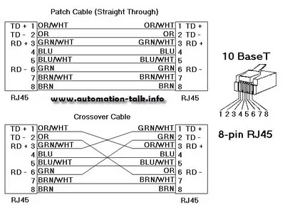
Allen Bradley Ethernet Cable Connections
If you are setting an Ethernet Connection for Allen Bradley PLC like SLC5/05 series and PLC5 you will first will require an Ethernet Cable for Connections.
Jun 16, 2011
Allen Bradley SoftLogix5800 System User Manual
SoftLogix5800 comes under large PLC system of Allen Bradley and used as a common control engine with a common development environment to provide high performance in an easy-to-use environment. This manual will provide you the information of Catalog Numbers 1789-L10, 1789-L30, 1789-L60. This manual will tell you about SoftLogix5800 Controller Installation Instructions, Instruction Execution, Connections for Produced and Consumed Tags, Configure Your System for a DeviceNet Network and its troubleshooting and lot more. Subscribe to Automation-Talk by Email.
Download Allen Bradley SoftLogix5800 System User Manual
How to Add PLC Network in WinCC Flexible 2008
Today in this article we are going to see that how we can set up a quick connection in WinCC Flexible 2008. To add a connection the procedure is very simple and you just have to follow some simple steps for adding up the PLC. How to Set Up Connection in WinCC Flexible 2008 :-
To add a PLC , open the WinCC Flexible 2008 and at the lest hand side Communication , click on it and "Connection" will be written there. Just Double click it to open and a table will open.
Here Define the Name of Communication and in the next tab select the type of PLC/Driver which you are going to connect.
At the bottom side of this same page you can select the type of HMI network and also the baud rate. Also there are section for defining the type of Network and PLC Device.
So this way we can easily set up a connection in WinCC Flexible 2008.
Subscribe to Automation-Talk by Email.
Jun 14, 2011
Matrikon OPC Server For Allen Bradley PLC
OLE Process control or OPC are still the major way for connecting different tags of your SCADA application, HMI or any other application which uses OPC to your PLC. If you are using Allen Bradley PLC's like PLC5, SLC500, Micrologix, and Control Logix then Matrikon OPC Server can be a good option for you to connect the PLC using OPC. This Allen Bradley OPC Server securely communicates over Ethernet, Serial, and "Blue Hose" to many Allen Bradley protocols such as: DF1, DH+ (Data Highway Plus),DH485, Ethernet/IP (Allen Bradley CIP). This is a very advance OPC server for Allen Bradley PLC which can grant and deny access to tags based on user login and is a useful security feature. Subscribe to Automation-Talk by Email.
You can download this Allen Bradley OPC server which is demo from below link. You may have to register to download OPC server for Allen Bradley PLC's.
Download Demo Matrikon OPC Server For Allen Bradley PLC
Jun 13, 2011
How to Create I/O Table in Omron CJ1M PLC
Every PLC Programming software has got the option for creating the I/O table or in other words to add the digital and analog cards with the CPU. We already discussed the analog card addition procedure in Delta PLC. Here in this post we will see the procedure for Creation of I/O Table in Omron PLC. Input - Output Table Creation in Omron PLC :-
To create an I/O Table , first of all create a new project and select the Proper PLC CPU accordingly. After that in the left hand side in Project workspace you will see an option of "I/O Tab & Unit Set up" ,double click on it to Open. Here select the Main Rack and then In options tab click on Create. This Will create the I/O table and will transfer all the connected I/O Units with PLC in the I/O table.
After creation of I/O table you will see that all connected Units with CPU will be displayed here in this section. After that click on Verify and we are done with the I/O table Part.
Important Note:- The I/O Table will only create if the PLC is Online and we have to be in Program / Stop Mode while creating the I/O Table.
See Below Video for Better Understanding.
Subscribe to Automation-Talk by Email.
PLC Programming for Labelling Machine
Labelling Machines find their applications in almost all the manufacturing Industries. Every product manufactured in the plant needs to be put a label having its description and so the automatic labelling machine have to be used for this purpose. Their can be various kind of labelling machines but today in this post we will discuss the PLC Programming for a simple Labelling Machine.
PLC Program for Automatic Labelling Machine :-
Before going in to the programming Details let us first understood the Hardware Part. The labelling Machine which are going to discuss has a Conveyor driven by AC Motor and one axis for labelling driven by stepping drive and stepping motor. There are two sensors for Product/Label Sensor. We will use one output for giving pulses to Steeper Drive.

Programming Procedure for Automatic Labelling M/C using Steeper Motor :-
Let us understand the Procedure for Labelling Machine operation. First of all we will give start command to the Inverter to start the conveyor for feeding the products. When the Product reaches the Sensor then the Product Sensor gives the signal to PLC , as soon as the PLC receives the signal the Output Y0 is on and gives pulses to steeper Drive and stamps the label on the product. Than wait for the signal of label sensor , as label sensor gives signal than the plc output the specified number of pulses and Stops. And than again wait for the signal of Product Sensor and the Process goes On.
Important Points to Remember for PLC Programming :-
The speed of the conveyor affects the labelling speed and also the start frequency of the steeper Motor should be adequate according to ramp up time. The time Interval between product sensor On signal and the PLC output should be adequate and also time interval label sensor ON and ramp-down stop should be accurate.
So implement the above steps for making the plc programming. The above logic can be implemented in any make plc.
Subscribe to Automation-Talk by Email.
Jun 10, 2011
Adding Analog I/O Module In Delta PLC
One of the most difficult task is to configure the Analog I/O Expansion Modules. Today in this post we will see that how simple it is to add the analog Modules in Delta PLC and define the settings for current and voltage Inputs. We will see the step by step procedure for this process. How to add analog card Modules in Delta PLC :-
To set up the analog Module , open the WPL Soft and then create a new project. After that click on the "Auxillary set up for Extension Modules" , a table will open. Here select the Analog Module Model number connected at the 0 position , similarly select the analog card model number for the other position. After selecting the model number click on the Set Up, A next page will open here select the I/O Mode setting and tick the write register (generate TO Instruction) , also at the bottom you will see the analog channel , here you can select the type of analog input as Current and Voltage. Select the Type of analog Input Accordingly and click to add to list.
After this select the CH1 average Input from the list and tick on Read Register ( generate from Instruction) and define the condition and the data word for storing the value and then add to list. Similarly if there is analog Output then define the analog channel output average value.
Hope after reading all this you can now add analog cards in Delta PLC easily. Dont forget to subscribe to get all latest updates
Subscribe to Automation-Talk by Email.
Jun 9, 2011
Delta HMI to PLC Modbus Communication Network
Delta HMI is compatible to communicate with PLC in Modbus and up to 32 PLC Can be connected in a network with HMI being the Master and the PLC as slaves.
HMI to PLC Modbus Network in Delta:-
Here we will consider that there are 3 plc in the network as slaves and One HMI as Master. So we will set up a Modbus ASCII network of one HMI(master) with 3 PLC’s (slaves).
In Delta Pin 1 will be D+ and Pin 6 will be D-, so make the wiring accordingly.
Setting Up Communication between ScreenEditor and WPLSoft:-
To set up the communication we need to define some of the Communication Parameters both at the PLC and HMI sides.
We have to define the same communication parameters on the HMI side. Open the Screen Editor and select the HMI model and in the Base Port controller select as Delta Controller ASCII.
We have made a sample PLC and HMI program, which you can download below.
Delta HMI to PLC Modbus Communication Sample Program
Follow Automation-Talk on Facebook.
Jun 8, 2011
Using Smart Ladder Input in CX - Programmer
Omron CX Programmer has the unique feature of Smart Ladder Input through which can directly write the Input or Output Name without even mentioning the I/O Address. Generally while making the PLC Program we have to Input the Physical I/O Address in the Ladder. But think if we just can make the PLC program by Inputting the Name of I/O. Its a good way to make the Program. We will see in this post that how we can do this in Omron CX - Programmer. Smart Ladder Input in Cx-Programmer :-
To learn the Smart Ladder Input Procedure , let us first understand what is smart Input is actually ? We all know that while making ladder program when we input a NO element then we have to input the Input address like 0.0 or 0.1 in case of Omron PLC. The same is the case is for Outputs. Think if we can already define in symbol table that which Input is at connected at which Physical address of PLC , like Gate Photo Sensor at 0.0 and Proximity Sensor at 0.1 and so on . So when we define the complete symbol table for all I/O then we just have to write the name which we define in Symbol table while making the PLC Ladder. Step by Step Procedure for Smart Ladder Input :-
First of all open the CX Programmer and create a New Project. After that you will see at the upper tab a icon of Smart Input Mode , click on it to activate It. Now the smart ladder Input is Activated. After that in the project Work space you will see symbols section ,click on it and after that add here all the Input and Outputs and Memory bits which you are going to Use in the PLC Ladder.
After adding all the Symbols names ,just open the plc ladder editor and when you input any NO contact the just simply write the name which you have defined in the symbol table for that particular Input. This way now we don't have to remember the address of all Inputs and Outputs. We can just simply make the PLC ladder by their names. Below is a video of all above which we have discussed.
Subscribe to Automation-Talk by Email.
Jun 7, 2011
Allen Bradley Power Flex 4M VFD User Manual
Allen Bradley Power Flex 4M AC drive is the the smallest and most cost-effective members of the PowerFlex family of drives. It comes in different- different power ratings and provide V/Hz control, slip compensation. It comes with Modbus facility and this manual will provide you with the basic information needed to install, start-up and troubleshoot the PowerFlex 4M Adjustable Frequency AC Drive. You must read understand Catalog Number Explanation so that on seeing it you can tell the specification of the drive. Subscribe to Automation-Talk by Email.
Download Allen Bradley Power Flex 4M VFD User Manual
Jun 3, 2011
Converting PLC Program for Other Model in Omron
Many a times it happens that we have a PLC Program made in advance and we need to download in to PLC. But the problem is that the PLC Program made is for some other model and the available PLC is different. Suppose we have a PLC Program made in CPM1A plc and we have to convert the Program to Omro CP1E PLC. SO in This tutorial we will see how to convert the PLC Code from one PLC to another in Omron. Changing PLC Model in Omron PLC Programming :-
To change the plc program from one plc to another is really a simple task in Omron. Just open the program which you want to convert to a different model , in the project work space you will see the PLC Model written , Just click on it , a window will open just change the plc model to one which u desire. Click on OK and the plc program will convert to desired plc selected by you.
Also after converting the PLC program check it for any errors. It may be possible that some instruction may no be supported in the new plc selected. So check for errors and if any correct the same.
We also have made a video for you so that it can be clearly understood by you. See below video for better understanding.
Subscribe to Automation-Talk by Email.
Mint Motion Language Programming Tutorial - Part 8
Today is the last part of the 8 part series of Baldor Mint Programming language Tutorial. We have tried to cover all the necessary topics in our tutorials. In this tutorial we will see some Keywords for advanced configuration and also some of error handling Tips, also a little light on interrupts and events.Advanced I/O Configuration Procedure in Mint :-
Inputs can be configured as level triggered or edge triggered. Level triggered inputs can be configured as active high or active low. Edge triggered inputs can be configured positive edge, negative edge or both.
INPUTMODE = 0x00001F :rem Inputs 0 to 4 edge triggered
INPUTACTIVELEVEL = 0x0003ffff :rem Inputs 0 to 17 active high
INPUTPOSTRIGGER = 0x00000401 :rem Inputs 0,10 +ve edge trig.
INPUTNEGTRIGGER = 0x00000402 :rem Inputs 1,10 -ve edge trig.
INSTATEX.x keyword can be used to decide if input is on/off independent of configuration
Digital outputs can be configured as active high or active low
ACTIVEOUTLEVEL = 0xFF0 :rem O/Ps 4 to 11 active high
Digital inputs can be assigned a specific use as well Forward limit switch, Reverse limit switch, Home switch, Error input, Stop switch .Digital outputs can be assigned as drive enable channels.
DRIVEENABLEOUTPUT.0 = 6 :rem Output 6 follows drive’s enable state. Workbench can be used to setup I/O configuration.Interrupts and Events in Mint:-
MINT allows a sub-routine or reserved label to be defined for each digital input, named EVENT IN0, EVENT IN1 etc...When an input is activated, if the corresponding interrupt routine exists, it will be called. The routine will be executed after the current statement except for GO, PAUSE and WAIT. Pre-defined interrupt routines also exist for Stop input, Fast input, Timer, Error and CAN events. An interrupt cannot interrupt itself - further calls to that interrupt are buffered. An interrupt can be interrupted by a higher priority interrupt, the lower priority one continuing once the higher priority one has finished.
Interrupts other than Event STOP and Event ONERROR can be enabled, disabled and checked using the following keywords….
EVENTDISABLE
Disable interrupts when a bit is set in the bitmask (bit pattern follows priority mapping - highest priority = bit 0)
Enable interrupts when a bit is cleared in the bitmask.
EVENTPENDING
A bit is set to indicate a pending event,Clear a bit to clear a specific event.
EVENTACTIVE
A bit is set to indicate an event is currently active.Asynchronous Errors in Mint MT:-
Asynchronous errors are produced at run time
In the range 0 - 502 and 3100 upwards - MintMT copies the error value to ERR keyword
Tree-structured Error hierarchy.
For example, Err 501 (Miscellaneous error) would require query of MISCERROR to diagnose
Axis errors are caused by axis motion (query AXISERROR for detail)
Hardware limit error, Software limit error, Exceeding maximum following error, External error input.
When an axis error occurs, the action taken can be user controlled
The error mode switches such as FOLERRORMODE, LIMITMODE, control what action an axis will take in the event of an error. The ONERROR event is called if defined and enabled. The ERR keyword is read to indicate the class of error. Axis errors are read with the AXISERROR keyword. Miscellaneous errors are read with MISCERROR. CAN errors are read with the CANSTATUS keyword. Clever use of ONERROR and tasks can keep ‘healthy’ axes running despite other errors.
We hope that you must have learned a lot of things about Baldor Servo Drives and Motion Controllers through this 8 part Series of Programming Tutorial.
Subscribe to Automation-Talk by Email.
Jun 2, 2011
Making Program in Delta C200 Inverter VFD

C2000 is a new multi purpose Inverter by Delta Electronics. This Inverter has the internal PLC for storing the Program and its logic can be made by same PLC Software. Also C2000 has got the Graphic display ,so its a perfect choice for applications that needs plc + Inverter + Graphic display i.e all in one. Delta C200 Inverter Features and Application :-
Delta C2000 Inverter has built in PLC function and the program memory is 10k steps. So C2000 is a boon for all stand-alone device applications. C2000 also supports CANOpen master communication.C2000 is available from 0.75~90kW for 230V series and 0.75~355kW for 460 series.
Sample Speed Control Program Application of C2000 :-
The programming of C2000 can be done by WPLSoft software , we will here see the simple multi speed application of C2000 and its programming. We will design a logic for 5 multi speed for C2000 and the speed will change periodically depending upon the time defined in the timer.
To make this logic just open the WPLSoft software and make a new project and select the PLC Model as VFD-C. M1040 is for Power on and M1025 is for RUN issuing command, so we have to set these two bits before giving the Frequency.
In this Program we are taking three multi speed and the each speed will change after the time defined in respective D Word. And after the third speed the first speed will resume and the process will go on.
Sample Multi Speed C2000 Program
Also Dont Forget To subscribe to get latest updates in PLC Programming and SCADA tutorials.
Subscribe to Automation-Talk by Email.
Download Delta HMI Software - Screen Editor
Delta Electronics HMI are also very popular in the industry because of there robust nature and also they are cheap HMI's. If you are having Delta DOP-A/AE/AS HMI series then Screen Editor ver V1.05.86 will be required by you which is 67.3 MB in size. The support multiple languages and is easy to program and create the screen for your Delta HMI's. You can get "Delta HMI Software" for free from their official Website. It is absolutely free for everyone and also does not require any sign Up's. Subscribe to Automation-Talk by Email.

Some of the Delta Screen Editor Versions are also compatible with Microsoft Windows Vista and Microsoft Windows 7, but not compatible with Windows XP. So if you are Using Window 7 you can use the different version of ScreenEditor which is given and it will solve your problem of not working in Window 7.
Delta DOP-A Series Software
Download Delta DOP-A HMI Software For Window 7 and Vista
Download Delta DOP-A HMI Software For Window XP
Delta DOP-B Series Software
Download Delta DOP-B HMI Software For Window7 & Vista
If you like our website and want more articles from us directly to your email address then do subscribe to Automation-Talk by Email for more and get free download-able HMI Software's.
Jun 1, 2011
Troubleshooting CP1E PLC Errors - PLC Tips
After Installing the PLC , sometimes there may be situation that some errors occur in PLC. So we have always be ready to handle out the PLC errors. There can be many issues related with PLC Problems , PLC Problem Troubleshooting Skills are boon to Site Engineers.Identifying PLC Errors :-
What to do when a PLC error Occur??? First of all check the Indicators on the front of CPU , every PLC has got a Error LED , just check that whether it is glowing or Not. Then Identify the Error i.e connect the PLC with the PLC Programming Software and see the Error Code. Next step after Identifying the error is to Implement countermeasures i.e take measures to resolve the error and also prevent the error to occur again. Checking Error Code in Omron CP1E PLC :-
Connect the communication cable and get online with CX-Programmer , in the project Space you will see the error Log, open it and a window will open and the current error will be displayed on it. Note down the error code written here.
Every Error that occur in PLC is stored in the PLC error Log and we can check even later on that which type of error occurred at what time. Every PLC Error in CP1E has three things associated with it i.e Error flag , Error information and Error Code. The error Log information in PLC is stored in the Auxiliary Area. In Omron CP1E PLC a maximum of 20 error are stored, if there are more than 20 error occur than the oldest error is deleted and new error takes its position. Auxiliary Area in Omron PLC CP1E for Error Logs :-
The Auxiliary Memory area in Omron PLC is from A100 to A199. For storing one Error 5 Auxiliary Area position are Required. For example the first error information will be stored from A100 to A104. In in A100 the Error Code will be there ,in A101 Error contents will be there , In A102 Minutes, seconds followed by Day, hour and Year, month in A103 and A104 respectively. And So on for the rest of 19 errors. Memory Errors in CP1E PLC :-
The Memory Error which occur in Omron Cp1E are stored in Other Auxiliary Memory Location. When a Memory error Occurs One or more bits in A403 will turn ON to indicate where the error has occurred. If A403.00 is ON then it indicates that a check sum error has occurred i.e power supply cut when backing up program. If A403.04 is ON then it means error occurred in PLC Setup.
Also there are many other types of error like CPU Errors and I/O Errors in CP1E which we will be discussing soon. Till then you can subscribe to get all latest updates. Subscribe to Automation-Talk by Email.


